TikZ-Feynman
[1]:
from pyfeyn2.feynmandiagram import FeynmanDiagram, Leg, Propagator, Vertex, Line,PDG
from pyfeyn2.render.latex.tikzfeynman import TikzFeynmanRender
from pyfeyn2.auto.position import feynman_adjust_points
import pyfeyn2
print(pyfeyn2.__version__)
2.1.0
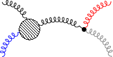
Simple Case
We set the positions of all vertices here.
[2]:
v1 = Vertex("v1").with_xy(-1, 0).with_shape("blob")
v2 = Vertex("v2").with_xy(1, 0).with_style("symbol : dot")

fd = FeynmanDiagram().add(
    v1,v2,
    Propagator(name="g",bend=True).connect(v1, v2),
    Leg(name="g",bend=True).with_target(v1).with_xy(-2, 1).with_incoming(),
    Leg(name="g",bend=True).with_target(v1).with_xy(-2, -1).with_incoming().with_class("notred"),
    Leg(name="g",bend=True).with_target(v2).with_xy(2, 1).with_outgoing().with_class("red"),
    Leg("myid1",name="g",bend=True).with_target(v2).with_xy(2, -1).with_outgoing()
)
Style
[3]:
fd = fd.with_rule("""
* {
    bend-direction: left;
    color: green;
}
""")
[4]:
fd.add_rules("""
.red {
    color: red;
}
.notred {
    color: blue;
}
#myid1 {
    color: gray;
}
[pdgid="21"] {
    color: black;
}
#myid2 {
    color: gray;
}
""")
fd.sheet.cssText
[4]:
b'* {\n bend-direction: left;\n color: green\n }\n.red {\n color: red\n }\n.notred {\n color: blue\n }\n#myid1 {\n color: gray\n }\n[pdgid="21"] {\n color: black\n }\n#myid2 {\n color: gray\n }'
[5]:
fd.to_xml()
[5]:
'<?xml version="1.0" encoding="UTF-8"?>\n<diagram id="FeynmanDiagram7" default_style="true" style="* { bend-direction: left; color: green } .red { color: red } .notred { color: blue } #myid1 { color: gray } [pdgid="21"] { color: black } #myid2 { color: gray }">\n <propagator id="Propagator8" pdgid="21" type="gluon" style="" bend="true">\n <name>g</name>\n <source>v1</source>\n <target>v2</target>\n </propagator>\n <vertex id="v1" style="" x="-1.0" y="0.0" shape="blob"/>\n <vertex id="v2" style="symbol: dot" x="1.0" y="0.0"/>\n <leg id="Leg9" pdgid="21" type="gluon" style="" bend="true" x="-2.0" y="1.0">\n <name>g</name>\n <target>v1</target>\n <sense>incoming</sense>\n </leg>\n <leg id="Leg10" pdgid="21" type="gluon" style="" class="notred" bend="true" x="-2.0" y="-1.0">\n <name>g</name>\n <target>v1</target>\n <sense>incoming</sense>\n </leg>\n <leg id="Leg11" pdgid="21" type="gluon" style="" class="red" bend="true" x="2.0" y="1.0">\n <name>g</name>\n <target>v2</target>\n <sense>outgoing</sense>\n </leg>\n <leg id="myid1" pdgid="21" type="gluon" style="" bend="true" x="2.0" y="-1.0">\n <name>g</name>\n <target>v2</target>\n <sense>outgoing</sense>\n </leg>\n</diagram>\n'
[6]:
tfd = TikzFeynmanRender(fd)
print(tfd.get_src())
\begin{tikzpicture}
\begin{feynman}
        \vertex (v1) [blob] at (-1.0,0.0) {};
        \vertex (v1clone) [] at (-1.0,0.0);
        \vertex (v2) [dot] at (1.0,0.0) {};
        \vertex (v2clone) [] at (1.0,0.0);
        \vertex (Leg9) [] at (-2.0,1.0);
        \vertex (Leg10) [] at (-2.0,-1.0);
        \vertex (Leg11) [] at (2.0,1.0);
        \vertex (myid1) [] at (2.0,-1.0);
        \diagram*{
                (v1) -- [gluon,black,bend left] (v2),
                (Leg9) -- [gluon,black,bend left] (v1),
                (Leg10) -- [gluon,blue,bend left] (v1),
                (v2) -- [gluon,red,bend left] (Leg11),
                (v2) -- [gluon,gray,bend left] (myid1),
        };
 \diagram*{};
\end{feynman}
\end{tikzpicture}

\documentclass[preview,crop,tikz]{standalone}%
\usepackage[T1]{fontenc}%
\usepackage[utf8]{inputenc}%
\usepackage{lmodern}%
\usepackage{textcomp}%
\usepackage{lastpage}%
%
\RequirePackage{luatex85}%
\usepackage[compat=1.1.0]{tikz-feynman}%
%
\begin{document}%
\normalsize%
\begin{tikzpicture}
\begin{feynman}
        \vertex (v1) [blob] at (-1.0,0.0) {};
        \vertex (v1clone) [] at (-1.0,0.0);
        \vertex (v2) [dot] at (1.0,0.0) {};
        \vertex (v2clone) [] at (1.0,0.0);
        \vertex (Leg9) [] at (-2.0,1.0);
        \vertex (Leg10) [] at (-2.0,-1.0);
        \vertex (Leg11) [] at (2.0,1.0);
        \vertex (myid1) [] at (2.0,-1.0);
        \diagram*{
                (v1) -- [gluon,black,bend left] (v2),
                (Leg9) -- [gluon,black,bend left] (v1),
                (Leg10) -- [gluon,blue,bend left] (v1),
                (v2) -- [gluon,red,bend left] (Leg11),
                (v2) -- [gluon,gray,bend left] (myid1),
        };
 \diagram*{};
\end{feynman}
\end{tikzpicture}
%
\end{document}
[7]:
tfd.render("test.pdf")
[7]:

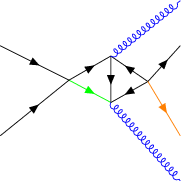
Complicated Case
We only set the positions of the Legs here.
[8]:
fd = FeynmanDiagram().with_rules(
    """ * {color: red;}
        [type=fermion] {color: blue; line: gluon}
        #p1 {color: green;}
        :not([type=fermion]) { color : black; line: fermion}""")
v1 = Vertex("v1")
v2 = Vertex("v2")
v3 = Vertex("v3")
v4 = Vertex("v4")
p1 = Propagator("p1").connect(v1, v2).with_type("gluon")
p2 = Propagator("p2").connect(v1, v3).with_type("gluon")
p3 = Propagator("p3").connect(v3, v2).with_type("gluon")
p4 = Propagator("p4").connect(v4, v3).with_type("gluon")
p5 = Propagator("p5").connect(v4, v2).with_type("gluon")
l1 = Leg("l1").with_target(v1).with_type("gluon").with_incoming().with_xy(-2, 1)
l2 = Leg("l2").with_target(v1).with_type("gluon").with_incoming().with_xy(-2, -1)
l3 = Leg("l3").with_target(v2).with_type("fermion").with_outgoing().with_xy(2, -2).with_class("blue")
l4 = Leg("l4").with_target(v3).with_type("fermion").with_outgoing().with_xy(2, 2)
l5 = Leg("l5").with_target(v4).with_type("gluon").with_outgoing().with_xy(2, 1)
l6 = Leg("l6").with_target(v4).with_type("gluon").with_outgoing().with_xy(2, -1)

l6.style.color = "orange"

fd.propagators.extend([p1, p2, p3, p4, p5])
fd.vertices.extend([v1, v2, v3, v4])
fd.legs.extend([l1, l2, l3, l4, l5, l6])
Now calculate the positions of vertices.
[9]:
ffd= feynman_adjust_points(fd)
[10]:
TikzFeynmanRender(ffd).render()
\begin{tikzpicture}
\begin{feynman}
        \vertex (v1) [] at (2.1734920634920636,2.84015873015873) ;
        \vertex (v1clone) [] at (2.1734920634920636,2.84015873015873);
        \vertex (v2) [] at (3.23984126984127,2.272539682539682) ;
        \vertex (v2clone) [] at (3.23984126984127,2.272539682539682);
        \vertex (v3) [] at (3.2361904761904765,3.4530158730158726) ;
        \vertex (v3clone) [] at (3.2361904761904765,3.4530158730158726);
        \vertex (v4) [] at (4.178253968253969,2.805079365079365) ;
        \vertex (v4clone) [] at (4.178253968253969,2.805079365079365);
        \vertex (l1) [] at (0.4285714285714286,3.7142857142857144);
        \vertex (l2) [] at (0.4285714285714286,1.4285714285714284);
        \vertex (l3) [] at (5.0,0.2857142857142857);
        \vertex (l4) [] at (5.0,4.857142857142857);
        \vertex (l5) [] at (5.0,3.7142857142857144);
        \vertex (l6) [] at (5.0,1.4285714285714284);
        \diagram*{
                (v1) -- [fermion,green] (v2),
                (v1) -- [fermion,black] (v3),
                (v3) -- [fermion,black] (v2),
                (v4) -- [fermion,black] (v3),
                (v4) -- [fermion,black] (v2),
                (l1) -- [fermion,black] (v1),
                (l2) -- [fermion,black] (v1),
                (v2) -- [gluon,blue] (l3),
                (v3) -- [gluon,blue] (l4),
                (v4) -- [fermion,black] (l5),
                (v4) -- [fermion,orange] (l6),
        };
 \diagram*{};
\end{feynman}
\end{tikzpicture}

[10]:
[ ]: